

How Transformers Change Voltage Explainer
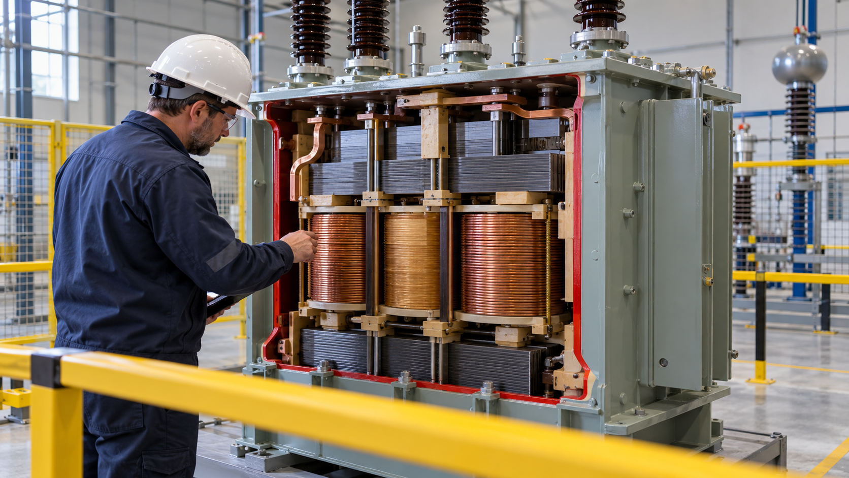
A transformer transfers electrical energy between circuits through a changing magnetic field. Alternating voltage applied to the primary winding drives an alternating current and magnetic flux in a shared core. That changing flux links the secondary winding and induces a voltage there. Ordinary transformers do not work from steady direct current because unchanging flux produces no continuous induced voltage.
For an ideal transformer, the voltage ratio equals the ratio of turns in the two windings. More secondary turns produce a higher voltage; fewer produce a lower one. Current changes in the opposite direction so input and output power remain equal in the ideal case. The device therefore trades voltage for current rather than creating energy.
A high-voltage, low-current transmission line loses less power to conductor resistance for a given delivered power. Grid transformers step generator voltage up for long-distance transmission and step it down in stages for distribution and use. Isolation transformers may keep nearly the same voltage while separating circuits electrically. Instrument transformers scale currents or voltages for measurement and protection.
Real cores guide magnetic flux but also dissipate energy. Alternating magnetization creates hysteresis loss, and induced currents within the core create eddy-current heating. Thin insulated steel laminations or ferrite materials reduce those currents. Copper resistance, leakage flux, vibration, and cooling systems contribute additional loss. Efficiency can be high, but heat still limits rating and life.
Too much voltage at a given frequency can push the core toward magnetic saturation. Current then rises sharply and waveform distortion and heating increase. Direct-current offset, harmonics, inrush during energization, and fault currents also stress equipment. Large power transformers use insulation, oil or other cooling media, bushings, tap changers, and protective systems designed for their operating environment.
The simple turns-ratio model is a starting point, not a full design. Load behavior, regulation, leakage inductance, frequency response, temperature, insulation aging, and fault forces all matter. Transformers made alternating-current power systems practical because voltage can be changed efficiently at fixed equipment, but safe use still depends on grounding, clearances, protection, and maintenance.
Changing primary current creates magnetic flux that induces secondary voltage.
Voltage follows the turns ratio while current changes in the opposite direction.
High transmission voltage reduces resistive loss for the same delivered power.
Core and winding losses become heat that cooling systems must remove.
Saturation, inrush, harmonics, and faults can drive damaging current.
Real transformer performance includes regulation, insulation, aging, and protection.
Explore more "Explainers"
Discover additional explainers across politics, science, business, technology, and other fields. Each explainer breaks down a complex idea into clear, everyday language—helping you better understand how major concepts, systems, and debates shape the world around us.